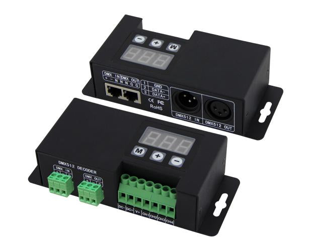
BC-853 DC 12V-24V Constant Voltage 3CH DMX512 Decoder for RGB LED Lights
BC-853 DC 12V-24V Constant Voltage 3CH DMX512 Decoder for RGB LED Lights
BC-853 DC 12V-24V Constant Voltage 3CH DMX512 Decoder for RGB LED Lights
Product Summary
1. Automatically adapts input voltage DC12V-24V.
2. Input standard DMX512 signal; 3-digital-display shows DMX address.
3. 3 channels output; 4096 grey scales each channel; logarithmic dimming; lamplight soft & stablewithout strobe flash.
4. Support master mode or slave mode;
5. 8 color changing modes and 10 speed scales in master mode .
6. Indicator of the DMX512 signal receiving status.
7. Power loss memory function.
8.Over current protection and short circuit protection.Wrong wiring protection at DMX prot.
9 .Multiple DMX512 signal interface.
Brief Introduction
This constant voltage DMX512 decoder is developed only for constant voltage LED lights. It adopts advanced mirco-computer technology to transfer standard DMX512/1990 signal to PWM signal. User can choose 1-3 output channels, 4096 Grey Scales. Multiple DMX512 signal interface.
Specifications
Product Model: 3CH DMX512 Decoder
Input voltage: DC12V-DC24V
Max load current: RGB:6A×3CH
Max output power: RGB:72W×3CH(12V)/RGB:144W×3CH(24V)
Grey Scale: 4096 levels×3
Input Signal: DMX512/1990
Output Signal: Constant Voltage PWM×3
Decode Channel: 3CH
DMX512 socket: XLR-3R port/ RJ45 port/terminal block
Dimension: L157×W65×H40(mm)
Weight (G.W): 450g
Basic Features
1. Automatically adapts input voltage DC12V-24V.
2. Input standard DMX512 signal; 3-digital-display shows DMX address.
3. 3 channels output; 4096 grey scales each channel; logarithmic dimming; lamplight soft & stablewithout strobe flash.
4. Support master mode or slave mode;
5. 8 color changing modes and 10 speed scales in master mode .
6. Indicator of the DMX512 signal receiving status.
7. Power loss memory function.
8.Over current protection and short circuit protection.Wrong wiring protection at DMX prot.
9 .Multiple DMX512 signal interface.
Safty Warnings
1. In order to use it properly and safety, please read user's manual carefully before installation.
2. Please don't install this controller in lightening, intense magnetic and high-voltage fields.
3. To reduce the risk of component damage and fire caused by short circuit, make sure correct connection.
4. Always be sure to mount this unit in an area that will allow proper ventilation to ensure a fitting temperature.
5. Check if the voltage and power adapter suit the controller.
6. Don't connect cables with power on; make sure a correct connection and no short circuit checked with instrument before power on.
7. Please don't open controller cover and operate if problems occur.
8. The manual is only suitable for this model, any update is subject to change with our prior notice.
Dimension

Operating Instruction


Wiring Diagram
1) Wiring diagram of Slave Mode

2) Wiring diagram of Master Mode: (only one decoder is allowed to work as master)

Exception Handles

After-Sales
From the day you purchase our products within 2 years, if being used properly in accordance with the instruction, and quality problems occur, we provide free repair or replacement services except the following cases:
1. Any defects caused by wrong operations.
2. Any damages caused by inappropriate power supply or abnormal voltage.
3. Any damages caused by unauthorized removal, maintenance, modifying circuit, incorrect connections and replacing chips.
4. Any damages due to transportation, breaking, flooded water after the purchase.
5. Any damages caused by earthquake, fire, flood, lighting strike etc. force majeure of natural disasters.
6. Any damages caused by negligence, inappropriate storing at high temperature and humidity environment or near harmful chemicals.
Product features
Product features
Materials and care
Materials and care
Merchandising tips
Merchandising tips
Share

